Boss Plow Wiring Diagram
Sometimes the cables will cross. According to earlier, the lines at a boss plow wiring diagram signifies wires.

Boss Plow Wiring Schematic Free Wiring Diagram
Lighting is required because the plow’s blade usually obstructs the vehicle’s original equipment optics.
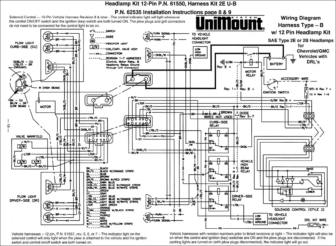
Boss plow wiring diagram. Boss rt3 v plow wiring diagram from www.untpikapps.com. Sometimes, the cables will cross. But, it doesn’t imply connection between the wires.
Rt3 wiring diagram rt3 wiring diagram. For example , if a module will be powered up also it sends out a signal of 50 percent the voltage and the technician would not know this, he would. When plowing dirt, gravel, or grass plow shoes should be lowered below the cutting edge surface to prevent the plow from digging into the plowed surface.
8 27 2004 9 59 47 pm. If not, the arrangement won’t work as it ought to be. For safety the boss includes cross over pressure relief to prevent damage by overstress.
Secure wiring harness (61) to light bar (13) as shown above. It consists of instructions and diagrams for different varieties of wiring methods along with other items like lights, windows, and so forth. Adjoining cable routes could be revealed approximately where specific receptacles or components must be on a common circuit.
Effectively read a cabling diagram, one provides to find out how the components inside the program operate. 12 boss plow wiring diagram truck side snow plow trucks snow plow truck fisher homesteader plow wiring diagram wiring diagram is a simplified good enough pictorial representation of an electrical circuit it shows the components of the circuit as simplified shapes and the skill and signal links amid the devices. 4 sample grade 2 vocabulary2 boss audio wiring diagram new bose radio wiring diagram wiring w in 2020 car audio installation car audio systems car stereo 107,9 03 87.5 rbds 87 50 9010 98,10 b asps 105,10 lou x phone keypad phone auto auto a 11:30.
There’ll be primary lines which are represented by l1, l2, l3, and so on. Kawasaki user manuals, snow plow parts, msc04754 boss snow plow, western snow plows. Hyd07044 with smarthitch2tm wiring diagram on page 18 of this manual.
Boss snowplows are manufactured by northern star industries and include quick mounting systems called smarthitches. See also ge refrigerator wiring diagram sample. Boss snow plows require power to operate the blade and lighting.
A wiring diagram is a simplified traditional photographic depiction of an electrical circuit. Boss straight blade joystick 9 pin square snow plow controller 906 engineering. Connect the plow side wiring harness to the hydraulic valve manifold as shown in figure 26.
On the other hand this diagram is a simplified version of the structure. Injunction of two wires is usually indicated by black dot on the junction of 2 lines. Rt3 wiring diagram rt3 wiring diagram.
It shows the elements of the circuit as streamlined forms, as well as the power and signal links between the devices. Boss v plow wiring diagram download. But it doesnt imply connection between the wires.
Boss rt3 v plow wiring diagram. Driveways) plow shoes can be raised up to increase cutting edge contact on the plowed surface. Boss snow plow wiring diagram.
Attach push frame attachment bar (3) to plow Collection of marine stereo wiring diagram. Wiring schematic wiring schematic g10004.
Electrical system wiring schematic (plow side) g10271. New holland t2410 t2420 tractor service manual new holland tractors. This isnbspset up to run.
A wiring diagram is a simplified standard photographic depiction of an electrical circuit. A wiring diagram is a kind of schematic which uses abstract pictorial symbols to exhibit all of the interconnections of components in a system. Electrical system wiring schematic (truck side) electrical system wiring schematic (truck side) g10272.
Boss part msc08001 2008 up vehicle side wiring harness 13 pin is used on all boss full sized truck plows. It will fit v straight blade plows with a 13 pin plow side harness. Boss snow plow solenoid wiring diagram wiring diagram is a simplified within acceptable limits pictorial representation of an electrical circuit.
You will need to wire the boss. Push frame attachment g10060 4. Each component should be set and connected with different parts in particular way.
It consists of directions and diagrams for different kinds of wiring methods and other products like lights, home windows, etc. Warn winch solenoid wiring diagram atv. Insert the unconnected ends of the plow wiring harness into the back of the coupler through the rubber grommet.
We have accumulated lots of photos, with any luck this image serves for you, and also assist you in discovering the solution you are looking for. 1987 polaris trail boss 250 wiring diagram electrical wiring diagram diagram electrical diagram. Wiring schematic wiring schematic g10004.
6 red black driver side in. Boss v plow wiring diagram.
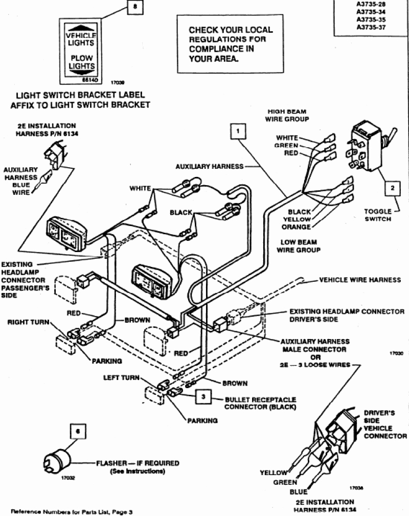
The Boss Snow Plow Wiring Diagram Gallery Wiring Diagram Sample
Plow Side 11pin to 13pin The largest community for snow plowing and ice management

Boss Snow Plow Wiring Diagram Boss Snow Plow Boss Snow Plow Wiring Diagram Motorcycle Review
Boss Plow Wiring Diagram Ford Collection

The Boss Snow Plow Wiring Diagram Gallery Wiring Diagram Sample
Boss Rt3 V Plow Wiring Diagram
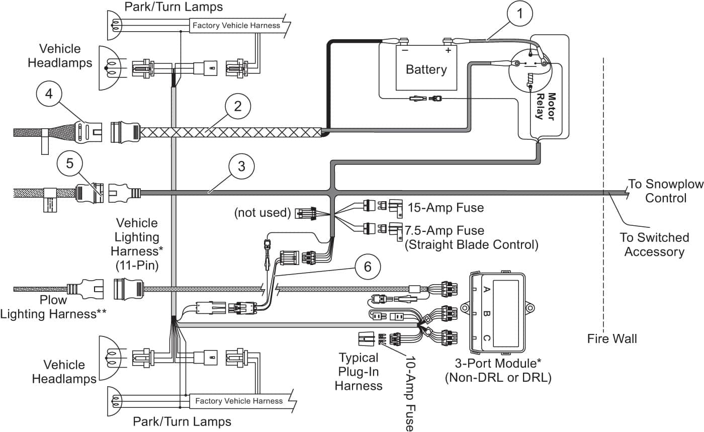
Boss V Plow Wiring Diagram Wiring Diagram

Boss V Plow Wiring Diagram Free Wiring Diagram
Boss RT1 vblade The largest community for snow plowing and ice management professionals. Find
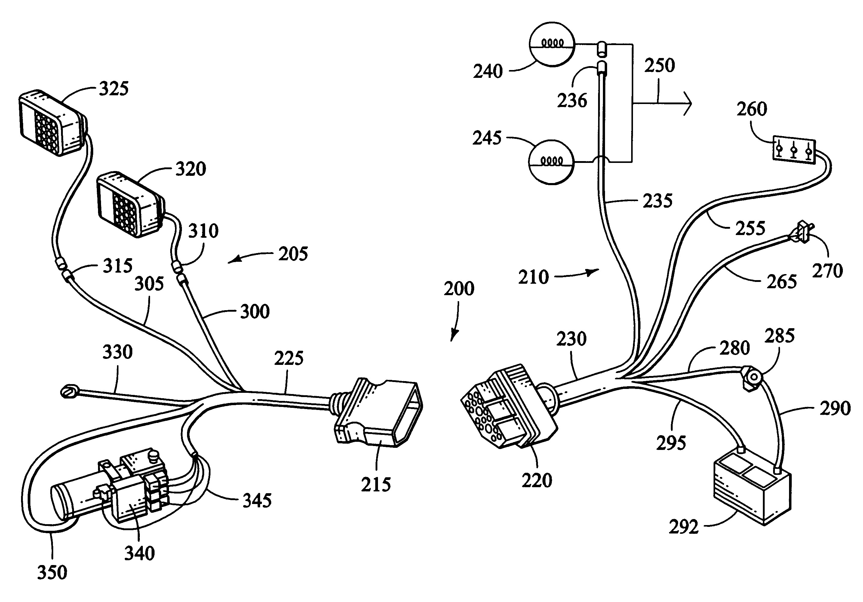
Boss Rt3 V Plow Wiring Diagram SHERRODSTAMPS

Boss Snow Plow Parts Diagram Wiring Diagram

HAVE A BOSS PLOW ON MY 2000 SILVERADO 1500. WENT OUT THIS EVENING AND NOW I HAVE NO HEADLIGHTS

Boss Snow Plow Wiring Diagram Western Plow Unimount Diagram Diagram Base Website Unimount

Boss Plow Wiring Schematic Free Wiring Diagram
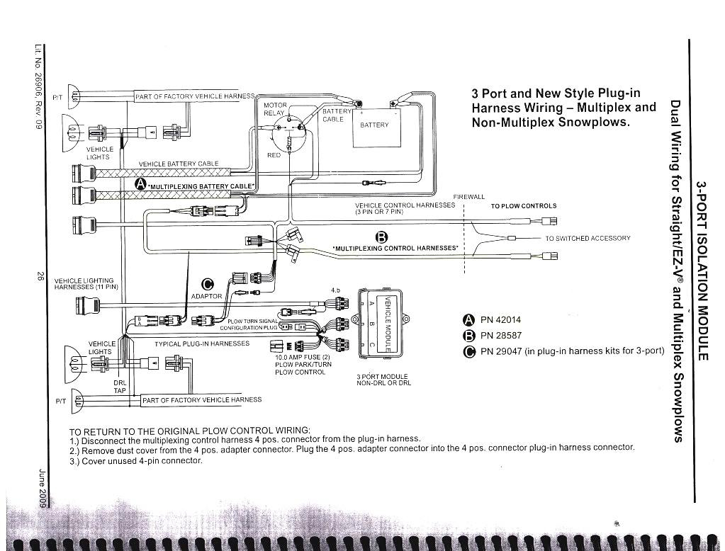
The Boss Snow Plow Wiring Diagram Gallery Wiring Diagram Sample

12+ Boss Plow Wiring Diagram Truck Side Truck Diagram Snow plow, Trucks, Plow truck


