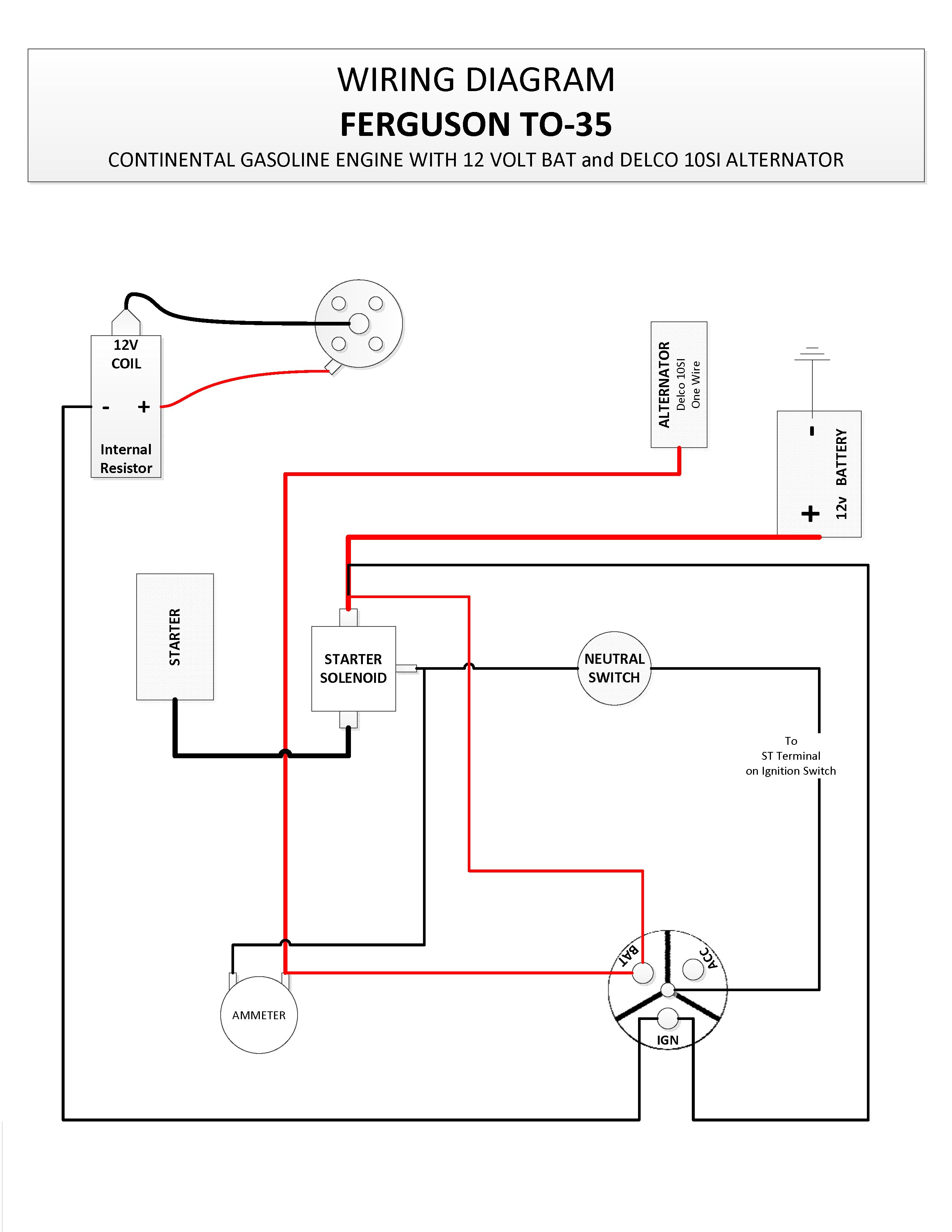
12 Volt Alternator Wiring Diagram
Perkins alternator wiring diagram kramag de. Gm 4 wire alternator wiring diagram.
2 Wire 12 Volt Alternator Wiring Diagram Collection
12 volt alternator installation amp operation manual.

12 volt alternator wiring diagram. Honda obd2 alternator wiring diagram. Club car wiring diagram 36 volt. Not merely will it assist you to accomplish…
Battery, still won't charge battery.fully. Electronic voltage regulators have been used on many cars since the mid 1970s. 220 volt hot tub wiring diagram.
My most sage advice is not only look at the diagram, yet understand how the constituents operate when within use. Wiring diagram for alternator with internal regulator. 12 volt alternator wiring diagram.
By david smith sep 22, 2016. The wiring hookup is the same for the cs 130 and cs 130d. It contains directions and diagrams for various varieties of wiring methods along with other things like lights, windows, etc.
12 volt alternator wiring diagram source: Common delco si series alternator wiring diagram. Charged battery started ran 15 minutes only 9 volts at battery posted by patrick gilmore on jan 24, 2014.
Wiring instructions for the gm delco remy internally regulated cs130 alternator. It contains guidelines and diagrams for various types of wiring strategies as well as other items like lights, windows, etc. 12 volt amp meter wiring diagram.
Connect alternator to balmar regulator wiring harness as indicated in wiring diagram included on page 12. 12 volt alternator wiring diagram. And connect the red wire to the output side of the alternator 10/32 stud, take the long wire and connect to the + side of the coil.
Ebay volt amp meter how to in this video we look at how you have to connect of the cheap ebay 100v 10a panel meters if you want to power it and read the valu. Assortment of farmall h 12 volt conversion wiring diagram. The alternator’s positive and ground cables should be sized according to the chart on page 3.
It includes guidelines and diagrams for different varieties of wiring strategies and other things like lights, windows, etc. Allows battery voltage from the ignition to flow to the alternator’s field coil during startup. Basic 12 volt wiring diagram wiring diagram is a simplified pleasing pictorial representation of an electrical circuitit shows the components of the circuit as simplified shapes and the gift and signal friends amongst the devices.
Perkins alternator wiring diagram netbook review com. Oct 24, · gahi's diagram is the correct way to wire a gm 10si/12si, and utilize all the benefits of that great. Variety of farmall h 12 volt conversion wiring diagram.
Perkins 4108 wiring diagram ybw. In their place goes the alternator, and that one wire going to the ammeter, now is the one wire coming from the alternator. Everyone on our customer care team is an experienced vw owner and works in our office.
We are commonly asked how to wire the delco si series alternators upon maintenance or upgrading from an older generator. Wire if needed and other necessary wiring. 12 volt alternator wiring diagram.
When you connect to the amp gauge you ll use 1 red wire and 1 black wire that will both carry a current. It’s supposed to assist all the typical user in developing a suitable method. Perkins wiring schematic boatdiesel com diesel generators blog fg wilson powered by perkins
At this point, let's think about the ammeter. 48v club car wiring diagram 48 volt. This voltage down the exciter wire to the alternator.
Club car wiring diagram 48 volt pdf. 12 volt alternator wiring diagram you will want a comprehensive expert and easy to know wiring diagram. 12 volt wiring diagram circuit diagram camper repair zig
Ford 8n 12 volt electrical diagram. It’s supposed to aid all the typical user in building a correct system. First, you can't run to the same side, since with the 12 volt.
You can save this graphic file to your own device. Read lutron dimmer 1 switch 1 light. With such an illustrative guidebook, you are going to be able to troubleshoot, stop, and total your projects easily.
One of the key differences is how the internal voltage regulator determines charge rate. First, you can't run to the same side, since with the 12 volt conversion, we are going to use negative ground rather than positive ground that all the old tractors used. Wiring diagram for alternator warning light.
Wiring diagram arrives with several easy to stick to wiring diagram directions. The purpose of a relay is to automate. While this series of unit often runs as a self exciting one wire, agricultural applications also used 3 wire connections to the alternator.
Subsequent diagrams is pretty simple, but using it in the opportunity of how the system operates is the different matter. Clicking this will make more experts see the question and we will remind you when it gets answered. These guidelines will likely be easy to grasp and apply.
2 alternator basic wiring diagram. 21 exciter wire battery light key switch to battery as mentioned before we need the correct voltage at the alternator for it to operate properly.
12 Volt Alternator Wiring Diagram Wiring Diagram
12 Volt Tractor Alternator Wiring Diagram For Your Needs
Charging System 12 Volt Alternator Wiring Diagram Collection
12 Volt Generator Voltage Regulator Wiring Diagram Alternator, Trailer wiring diagram
12 Volt Alternator Wiring Diagram Wiring Diagram
3 Wire 12 Volt Alternator Wiring Diagram Collection
12 Volt Alternator Wiring Diagram Wiring Diagram
12 Volt Alternator Wiring Diagram Wiring Diagram
12 Volt Delco Alternator Wiring Diagram Car alternator, Alternator
12 Volt Alternator Wiring Diagram Wiring Diagram
Wiring Diagram 12 Volt Generator
Basic 12 Volt Alternator Wiring Diagram NZALALA
12 Volt Alternator Wiring Diagram — UNTPIKAPPS
12 Volt Alternator Wiring Diagram Database Wiring Diagram Sample
12 Volt Alternator Wiring Diagram — UNTPIKAPPS
12 Volt Alternator Wiring Diagram Wiring Diagram
Ford 9n 12 Volt Conversion Wiring Diagram Collection