Mosfet Amplifier Circuit Diagram With Pcb
Heat sink is necessary for the mosfets. 240w 8ohm, 350w 4ohm go.
100w amplifier circuit with PCB
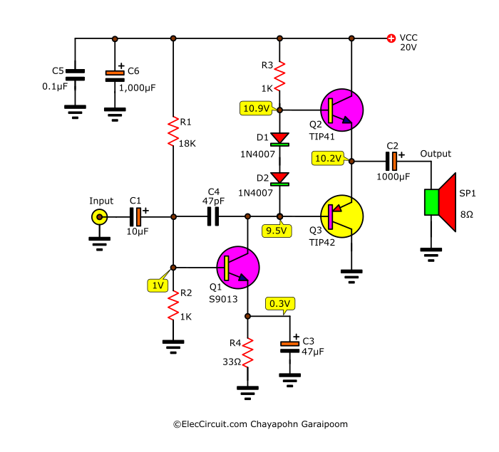
Q7 and q8 transistors make the power amplifier of class ab.
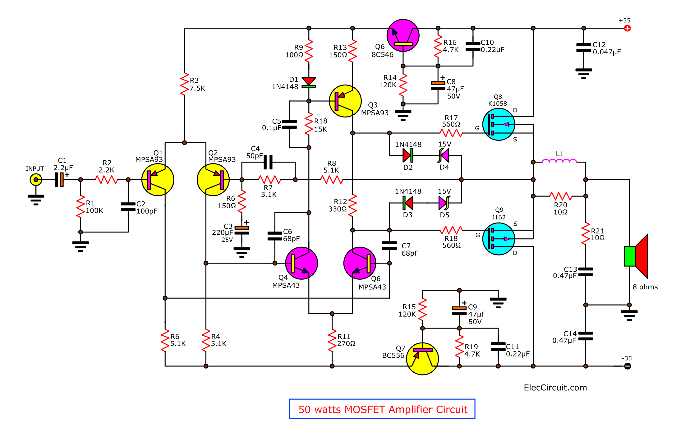
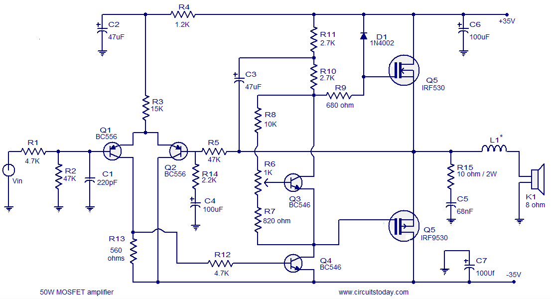
Mosfet amplifier circuit diagram with pcb. Referring to the circuit diagram, we see that the input stages primarily consists of two differential amplifiers. The shown mosfet amplifier design circuit will happily output a 35 watts rms into an 8 ohm load. This driver circuit stabilized bias in output stage.
The design being symmetrical produces negligible distortions. Assemble the circuit on a good quality pcb. C6 and c7 must be rated 50v;
2n3055 amplifier circuit with pcb; About mosfet amplifier diagram circuit. 100w mosfet power amplifier circuit operation:
The circuit has been assembled and tested with very good performance. Let’s try to analyze the circuit details: 200w mosfet amplifier powered using four piece of irfp250n.
You should build two similar circuits for stereo audio application. Assemble the circuit on a good quality pcb. It is designed to maximize the magnitude of the power f given input signal.
Other electrolytic can be 10 or 15v. Voltage amplifier/driver biased with 30ma. The prototype was analyzed only for signal frequencies around 1 khz.
The circuit has been assembled and tested with very good performance. 55w rms otl integrated amps build easily; 13+ mosfet amplifier circuit diagram.
Lm3876 | 60 watt amplifier circuit in stereo; C6 and c7 must be rated 50v; It makes the sound quality is very good.
This 200 watt amp mosfet amplifier schematic circuit is a class d high power audio amplifier based on discrete components. While r1 is used to adjust the output voltage. 50w ocl mosfet amps—using k1058 + j162;
The prototype amplifier appears to perform incredibly well, specifically only once we notice the fairly simple design of the unit. All the details of fet400 mosfet amplifier circuit diagram, pcb, layout description and high resolution images (hq) have 8 ohm speakers with 263 watts rms and 350 watts into 4 ohms 6 ohms and 406 watts rms power can give. The fuses are used in the circuit for a safety basis.
I have made the simple basic audio amplifier circuit in the pcb for making the circuit as simple as possible. In the mosfet power amplifier circuit, capacitor c8 is the input decoupling capacitor. 1000 watt audio amplifier with transistors 2sc5200 and 2sa1943 dt 4233 1000w subwoofer amplifier circuit diagram audio amplifier circuits.
This amplifier can be used for practically any application that requires high power, low noise, distortion and excellent sound. Other electrolytic can be 10 or 15v. 50 watts mosfet amplifier circuit diagram.
100 watt power amplifier circuit using mosfet. Resistor r3 and r2 are used to set the gain. The ac signal is coupled to q1’s base via a coupling capacitor, while the feedback signal is sent to q2’s base via r5 and r6.
Here the schematic diagram of 800 watt audio power amplifier with mosfet for final amplification. Exelent stability without oscilation, hum and noise, sound great. For l1 make 12turns of enameled copper wire on a 1cm dia:
30 mhz 100w mosfet power amplifier. A 100w mosfet power amplifier circuit based on irfp240 and irfp9240 mosfets is shown here. It is designed to maximize the magnitude of the power f given input signal.
Build one first for performance testing to ensure that this circuit really wongking well with great audio performance. Power amplifier is the part of audio electronics. For l1 make 12turns of enamelled copper wire on a 1cm dia:
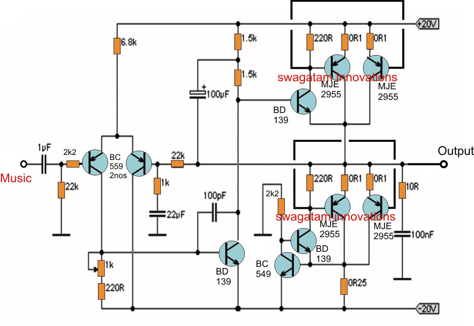
0 152 2 minutes read. Here is a circuit that uses a mosfet amplifier amplicable for subwoofer as the main booster, or the basis of this boosteramplifier. The differential amplifier circuit is made up of pnp transistors, with one receiving the input ac signal and the other receiving the output signal through feedback.
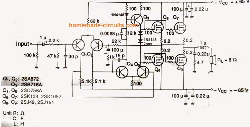
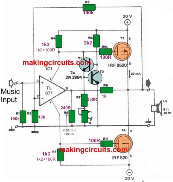
This outstanding 250 watt mosfet amplifier circuit can be used as a dj amplifier in concerts, parties, open grounds etc. 100w basic mosfet amplifier circuit diagram and pcb layout pcb layout the first amplify consists of transistors t1 and t2 are constructed as a differential amplifier, which is the source of current is adjustable with a resistor r3. This 200w mosfet amplifier circuit designed for single or mono audio channel application.
R20 is used to restrict the input current for transistor q1. In sound electronics, the operational amplifier increases the voltage of the signal, but unable to provide the current, which is required to drive a load. Assemble the circuit on a good quality pcb.
Assemble the circuit on a good quality pcb. The total harmonic distortion will not be more than around 0.05%.
200 watt mosfet amplifier circuit to 300W on class G
Simple 20 watt Amplifier Circuit
100W MOSFET power amplifier The Circuit

600 Watt Mosfet Power Amplifier Diagram with PCB Gallery

400W High Power Mosfet Amplifier Gambar Skema

50w MOSFET amplifier circuit OCL using K1058 + J162
Popular Mosfet Audio Amplifier CircuitsCircuit Diagrams
Mosfet Power Amplifier 100W RMS 8 Ohm Electronic Circuit

DIY 100 Watt MOSFET Amplifier Circuit Homemade Circuit
Schematic Diagram 200W Subwoofer Amplifier Circuit

Pin on Amplifier

Designing a MOSFET Power Amplifier Circuit
1000W Power Amplifier 2SC5200 2SA1943 Electronic Circuit

200W Power Amplifier Schematic Diagram & PCB Design

DIY 100 Watt MOSFET Amplifier Circuit Homemade Circuit
DIY 100 Watt MOSFET Amplifier Circuit Homemade Circuit
Popular Mosfet Audio Amplifier CircuitsCircuit Diagrams
2N3055 amplifier circuit diagram, 30w OCL integrated PCB
Collection Scheme Audio Power Amplifier High Power MOSFETs
